

There are a few variables that can control what your linetypes look like in AutoCAD.
LTSCALE - This variable is like a preview of what your linetypes will look like at a certain scale in Model Space.
PSLTSCALE - This is the variable that control what your linetypes will look like in Paper Space.
CELTSCALE - The is the current element linetype scale. If you set this in your properties dialog box, every linetype will have a specific linetype scale that will be multiplied by LTSCALE or PSLTSCALE.
The good news about all of this is, by using Scale Manager, you do not have to remember any of these. Just thought you would like to know what Scale Manager is doing for you.
Showing posts with label Program - AutoCAD. Show all posts
Showing posts with label Program - AutoCAD. Show all posts
Wednesday, March 7, 2012


Tuesday, October 25, 2011
TBG Scale Manager
Scale Manager is a tool that we use set our
What Scale Manager doesn't do
Scale Manager Layout
1. Unit Values - Switch between Architectural Units, Engineering Units, and Metric Units. These are the units you will use to draft your drawings. You should only switch the units once to start working. They should not be modified after starting work in drawing.
2. Layer Categories or A,B,C Area - This is an additional layer division that allows for 3 different categories for layers on the same scale in the form of A, B, and C layers. (Example: 0A-dim-A-0010, 0A-dim-B-0010, and 0A-dim-C-0010.) All layers are default "A" category unless some other category is selected. Scale Manager will add these to your layer names.
3. Scale and Dimension Styles Area - This area is where you will set the scale and also it will determine what units your dimension will be shown in. This comes into play with Metric Units more than Architectural or Engineering Units. Scale Manager will add the current scale to certain objects layer names. Decimal and Metric units are easy to decipher, but the architecture units are a little harder read because they are in decimal format. for instance 3/4" = 0016.
How to Use Scale Manger
1. Command: : "SM"
2. Select your Units.
3. Select your Scale
4. Should not have to hit "OK" after selecting scale.
Working With Metric Scales
1. Select the units you will be drawing in. You should not toggle units when drawing in metric. Usually plans are drawn in meters and details are drawn in millimeters. If you decide to toggle units (not scales) you will need to rescale your drawings.
2. When selecting scales also consider what dimension style you would like to see them in. For instance if you are drawing in MM but want to see dimensions in Meters you would select a scale from the Meter Dimensions column.
When working with metric scales, we have chosen to use dimscales that are scaled from imperial units. Meaning dimscales are not set to 1, 5, 10, 15, etc... when working in metric units, they are instead set to 25.4, 127, 254, 381, etc... The reason for this is that all the current blocks, linetypes, hatch patterns, and notes have been created in imperial units and therefore will need what I call a "dirty scale" to scale them correctly instead of a "clean scale" of 1, 5, 10, 15. So do not be worried if the dimscale is not set to 1, 5, 10, 15, etc..
Layer Categories
Layer categories were created to provide a way to see different annotation sets at the same scale. Please refer to the article on AutoCAD Layer Names. A common scenario... A pool plan has deck dimensions at 10scale for one drawing and pool fence layout dimensions at 10scale in the same drawing. When viewing this drawing in a sheet plan, if the dimensions were drawn on the same layer, you would not be able to freeze the deck dimensions and see only the fence dimensions because they were created on the same layer. That is where using categories become useful. Now you can have dimensions for the deck on "A" category and fence dimensions on a "B" category.
Selecting a Category
If a Category is never set then it will always default to "A" category.
Otherwise:
Selecting "A" category will show ALL "A" category objects and make the "A" category current for all new items and freeze the category "B" and "C" layers.
Selecting "B" category will show ALL "B" category objects and make the "B" category current for all new items and freeze the category "A" and "C" layers.
Selecting "C" category will show ALL "C" category objects and make the "C" category current for all new items and freeze the category "A" and "B" layers.
View All "ABC"
This will thaw all ABC layers no matter what the scale is.
View Current ABC
View Current ABC will show the current category at the current scale.
To see a specific scale in A, B, or C categories.
1. Set the scale you would like to see first.
2. Select "A","B",or "C" category to show ALL "A","B", or "C" category items.
3. Select "View Current 'ABC'" and click "OK" to show the A, B, or C layers at the current scale.
View All Dimscale
This will show all layers with the current dimscale. Matchlines, Reference Lines, Utility Text, and Street Text usually do not have A, B, or C categories and this command will thaw them as well.
Software Bug:
If current dimscale is annotative, Scale manager will not close and will show an error on the command line. It will also give you an error when switching between model space and paper space. To fix this either set a dimstyle that is not annotative current or modify the current dimstyle. To modify the current dimstyle, type "dimstyle" on the command line and select the current dimstyle. Click the modify button. Select the "Fit" tab. and uncheck the annotative box. Save the dimstyle.
- Dimension Styles (DIMSTYLE),
- Text Height (TEXTSIZE),
- Layer Names, Dimscale (DIMSCALE),
- Text Style (TEXTSTYLE),
- Linetype Scale(LTSCALE),
- Units (DDUNITS),
- Insert Units (INSUNITS).
What Scale Manager doesn't do
- When the scale is changed, it will not change the scale of what has already been drawn.
- Viewport Scales are not controlled by scale manager
- Annotation scales (if any) will not be affected
| ||
| From TBG Two Minute Training |

1. Unit Values - Switch between Architectural Units, Engineering Units, and Metric Units. These are the units you will use to draft your drawings. You should only switch the units once to start working. They should not be modified after starting work in drawing.
2. Layer Categories or A,B,C Area - This is an additional layer division that allows for 3 different categories for layers on the same scale in the form of A, B, and C layers. (Example: 0A-dim-A-0010, 0A-dim-B-0010, and 0A-dim-C-0010.) All layers are default "A" category unless some other category is selected. Scale Manager will add these to your layer names.
3. Scale and Dimension Styles Area - This area is where you will set the scale and also it will determine what units your dimension will be shown in. This comes into play with Metric Units more than Architectural or Engineering Units. Scale Manager will add the current scale to certain objects layer names. Decimal and Metric units are easy to decipher, but the architecture units are a little harder read because they are in decimal format. for instance 3/4" = 0016.
How to Use Scale Manger
1. Command: : "SM"
2. Select your Units.
3. Select your Scale
4. Should not have to hit "OK" after selecting scale.
| ||
| From TBG Two Minute Training |

1. Select the units you will be drawing in. You should not toggle units when drawing in metric. Usually plans are drawn in meters and details are drawn in millimeters. If you decide to toggle units (not scales) you will need to rescale your drawings.
2. When selecting scales also consider what dimension style you would like to see them in. For instance if you are drawing in MM but want to see dimensions in Meters you would select a scale from the Meter Dimensions column.
When working with metric scales, we have chosen to use dimscales that are scaled from imperial units. Meaning dimscales are not set to 1, 5, 10, 15, etc... when working in metric units, they are instead set to 25.4, 127, 254, 381, etc... The reason for this is that all the current blocks, linetypes, hatch patterns, and notes have been created in imperial units and therefore will need what I call a "dirty scale" to scale them correctly instead of a "clean scale" of 1, 5, 10, 15. So do not be worried if the dimscale is not set to 1, 5, 10, 15, etc..
| ||
| From Drop Box |

Layer categories were created to provide a way to see different annotation sets at the same scale. Please refer to the article on AutoCAD Layer Names. A common scenario... A pool plan has deck dimensions at 10scale for one drawing and pool fence layout dimensions at 10scale in the same drawing. When viewing this drawing in a sheet plan, if the dimensions were drawn on the same layer, you would not be able to freeze the deck dimensions and see only the fence dimensions because they were created on the same layer. That is where using categories become useful. Now you can have dimensions for the deck on "A" category and fence dimensions on a "B" category.
Selecting a Category
If a Category is never set then it will always default to "A" category.
Otherwise:
Selecting "A" category will show ALL "A" category objects and make the "A" category current for all new items and freeze the category "B" and "C" layers.
Selecting "B" category will show ALL "B" category objects and make the "B" category current for all new items and freeze the category "A" and "C" layers.
Selecting "C" category will show ALL "C" category objects and make the "C" category current for all new items and freeze the category "A" and "B" layers.
View All "ABC"
This will thaw all ABC layers no matter what the scale is.
View Current ABC
View Current ABC will show the current category at the current scale.
To see a specific scale in A, B, or C categories.
1. Set the scale you would like to see first.
2. Select "A","B",or "C" category to show ALL "A","B", or "C" category items.
3. Select "View Current 'ABC'" and click "OK" to show the A, B, or C layers at the current scale.
View All Dimscale
This will show all layers with the current dimscale. Matchlines, Reference Lines, Utility Text, and Street Text usually do not have A, B, or C categories and this command will thaw them as well.
Software Bug:
If current dimscale is annotative, Scale manager will not close and will show an error on the command line. It will also give you an error when switching between model space and paper space. To fix this either set a dimstyle that is not annotative current or modify the current dimstyle. To modify the current dimstyle, type "dimstyle" on the command line and select the current dimstyle. Click the modify button. Select the "Fit" tab. and uncheck the annotative box. Save the dimstyle.
Wednesday, October 13, 2010
AutoCAD 2011 - Staus Bar Icons
If you want to change your status bar in AutoCAD 2011 from icons to text, follow these instructions.
1. Find the status bar icons at the bottom center of the AutoCAD screen.
2. Right click on the status bar to bring up the menu options. Click on the "Use Icons" menu to either select or unselect this option.
3. Now all of your status bar icons should be in text format.
1. Find the status bar icons at the bottom center of the AutoCAD screen.
 |
| From Drop Box |
2. Right click on the status bar to bring up the menu options. Click on the "Use Icons" menu to either select or unselect this option.
 |
| From Drop Box |
3. Now all of your status bar icons should be in text format.
 |
| From Drop Box |
Tuesday, May 25, 2010
Pavestone Hatch Patterns
The Pavestone hatch patterns are now included in the list of AutoCAD hatch patterns. They are custom hatch patterns so you will have to go to the custom tab to select the Pavestone pattern you need. Use the scale of 1" for architectural units or .08333 for decimal engineering units.
Click here to view Pavestone's list of hatch pattern names.
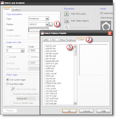
1. Click the Browse button.
2. Click the "Custom" tab.
3. Select the pattern you need, then click OK.
Click here to view Pavestone's list of hatch pattern names.
1. Click the Browse button.
2. Click the "Custom" tab.
3. Select the pattern you need, then click OK.
Tuesday, February 16, 2010
Xrefs - Overlay vs. Attachment
The Difference Between "Overlay" and "Attachment"
"Overlay"
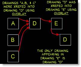
Using the "Overlay" method means that the referenced drawing you are inserting will be viewed in the current drawing only. It will not follow the current drawing to the next drawing. It is the simplest form of reference file and as a result it is the most used method of inserting a xref into a drawing. This is a nice method to use when handling a drawing or two from a consultant or in house drawings. Notice in the example below that Drawings A, B, and C are inserted using the "Overlay" method into drawing D. Then D is inserted into drawing E and notice that A, B, and C do not follow drawing D when inserted into drawing E.
"Attachment"
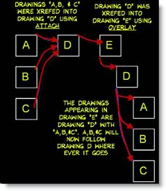
Using the "Attachment" method means that the drawing you are inserting can be viewed the current drawing and all other drawings you insert the current drawing into. This a good method when you have complex drawings that have many other referenced files. A good example is an architect's drawing that has three or more drawings referenced into it (like difference floors). Notice in the example below that Drawings A, B, and C are "Attached" into drawing D. Then D is inserted into drawing E (also like above), but he difference is that A, B, and C now follow drawing D when inserted into drawing E.
How Can I Make My External References Overlay or Attached?
Method #1
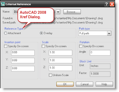
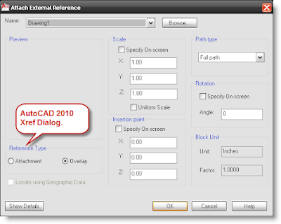
Choose either "Overlay" or "Attach" from the xref dialog box when inserting the drawing. (As shown below for AutoCAD 2008 and 2010). The option will lie in the "Reference Type" frame.
Method #2
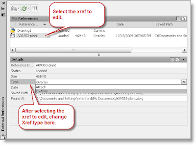
Use the xref palette to change "Type" of xref (shown below) if they are already inserted into your drawing. You will not be able to change nested xrefs. This option will be grayed out if this is the case.
"Overlay"
Using the "Overlay" method means that the referenced drawing you are inserting will be viewed in the current drawing only. It will not follow the current drawing to the next drawing. It is the simplest form of reference file and as a result it is the most used method of inserting a xref into a drawing. This is a nice method to use when handling a drawing or two from a consultant or in house drawings. Notice in the example below that Drawings A, B, and C are inserted using the "Overlay" method into drawing D. Then D is inserted into drawing E and notice that A, B, and C do not follow drawing D when inserted into drawing E.
"Attachment"
Using the "Attachment" method means that the drawing you are inserting can be viewed the current drawing and all other drawings you insert the current drawing into. This a good method when you have complex drawings that have many other referenced files. A good example is an architect's drawing that has three or more drawings referenced into it (like difference floors). Notice in the example below that Drawings A, B, and C are "Attached" into drawing D. Then D is inserted into drawing E (also like above), but he difference is that A, B, and C now follow drawing D when inserted into drawing E.
How Can I Make My External References Overlay or Attached?
Method #1
Choose either "Overlay" or "Attach" from the xref dialog box when inserting the drawing. (As shown below for AutoCAD 2008 and 2010). The option will lie in the "Reference Type" frame.
Method #2
Use the xref palette to change "Type" of xref (shown below) if they are already inserted into your drawing. You will not be able to change nested xrefs. This option will be grayed out if this is the case.
Wednesday, February 3, 2010
How To Import Excel Spreadsheets Into AutoCAD
I have had a lot of questions lately about how to import excel spreadsheets into an AutoCAD drawing. Here is the method that Autodesk suggests. They highly discourage copying and pasting as an OLE object, and using the insert OLE object due to it's inconsistencies.
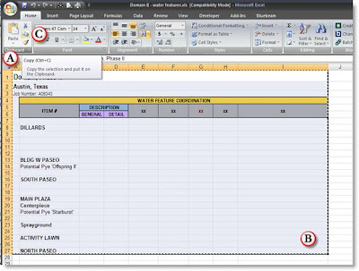
A. Open the Spreadsheet
B. Select the area to copy
C. Copy the Selection (CTRL+C)
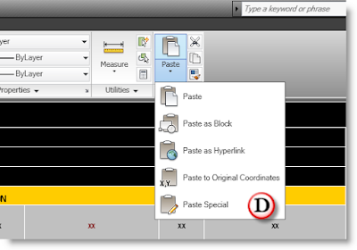
D. Open the CAD Drawing and to the Pulldown Edit->Paste Special (or Ribbon Home->Clipboard->Paste->Paste Special)
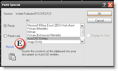
E. In the Paste Special Dialog box select "AutoCAD Entities".
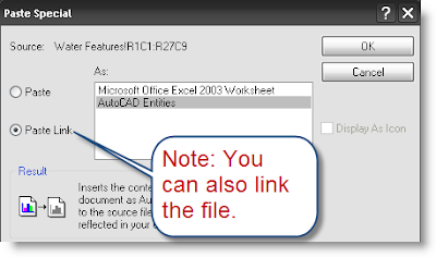
Note: you can select "Paste Link" and then select AutoCAD Entities if you want to link the file.
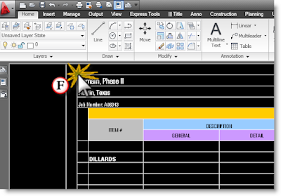
F. Select the Insert point, then the excel spread sheet will become a table. You can then create a table style for your Excel documents that will customize the look with the table style or you can leave the table with the same formatting as the Excel spreadsheet.
FAQ'S ABOUT INSERTING EXCEL SPREADSHEETS
1. Can I change the look of the spreadsheet?
- Yes you can change the look of the spreadsheet by using the "TABLESTYLE" command. This will bring up a dialog to create a table style that can be applied to the excel spreadsheet. Otherwise the table will have all the same properties as the excel spreadsheet including color, fonts, background fill, and cell lines.
2. What does the padlock and chain link icon mean when I am working with a table?
- The padlock means that the spreadsheet is locked and to edit the data in the spreadsheet you will need to update the data in the excel version and it will be updated in the AutoCAD table version.
- The chain link means that it is linked to a file. When a file is linked, the table is locked. However, you can lock a table without it being linked.
3. What should I name my Tables?
- They should start with "TBG-" and then a description. This will help differentiate your table with other consultant's tables.
4. How do I know when there is an update for my table and how do I update it?
- There will be a link in the lower right hand corner of drawing. If you right click on that link there will be an option to "Update Links". This will update all linked data in your drawing. Right now there is no way to update individual linked objects.
5. What is a quick way to edit the linked spreadsheet without having to browse to the file?
- Go to the reference palette and right click on the spreadsheet. There should be an option to open the linked file. (When finished you can also right click and update links as well).
A. Open the Spreadsheet
B. Select the area to copy
C. Copy the Selection (CTRL+C)
D. Open the CAD Drawing and to the Pulldown Edit->Paste Special (or Ribbon Home->Clipboard->Paste->Paste Special)
E. In the Paste Special Dialog box select "AutoCAD Entities".
Note: you can select "Paste Link" and then select AutoCAD Entities if you want to link the file.
F. Select the Insert point, then the excel spread sheet will become a table. You can then create a table style for your Excel documents that will customize the look with the table style or you can leave the table with the same formatting as the Excel spreadsheet.
FAQ'S ABOUT INSERTING EXCEL SPREADSHEETS
1. Can I change the look of the spreadsheet?
- Yes you can change the look of the spreadsheet by using the "TABLESTYLE" command. This will bring up a dialog to create a table style that can be applied to the excel spreadsheet. Otherwise the table will have all the same properties as the excel spreadsheet including color, fonts, background fill, and cell lines.
2. What does the padlock and chain link icon mean when I am working with a table?
- The padlock means that the spreadsheet is locked and to edit the data in the spreadsheet you will need to update the data in the excel version and it will be updated in the AutoCAD table version.
- The chain link means that it is linked to a file. When a file is linked, the table is locked. However, you can lock a table without it being linked.
3. What should I name my Tables?
- They should start with "TBG-" and then a description. This will help differentiate your table with other consultant's tables.
4. How do I know when there is an update for my table and how do I update it?
- There will be a link in the lower right hand corner of drawing. If you right click on that link there will be an option to "Update Links". This will update all linked data in your drawing. Right now there is no way to update individual linked objects.
5. What is a quick way to edit the linked spreadsheet without having to browse to the file?
- Go to the reference palette and right click on the spreadsheet. There should be an option to open the linked file. (When finished you can also right click and update links as well).
Tuesday, February 2, 2010
Color and Linetype Standards
Linetype Standards
We don't have many office standards governing linetypes, just three really.
1. All Colors for objects (except for details) should be "ByLayer".
1. All Linetypes for objects (except for details) should be "ByLayer".
2. All Linetypes (except for details) should have a scale of 1. (Variable "celtscale" or current element linetype scale.)
That's not too hard.
Why can I not match properties to a linetype?
There are a few reasons:
1.) Either the MatchProp settings do not include Linetype
2.) We do not have that linetype in our library and will not match properties to it.
Why are details exempt from being ByLayer?
The main reason that object colors and linetypes are exempt from being ByLayer in details is because details are not externally referenced into other types of drawings. Details are drawn as what you see is what you get.
Why can I not see my linetype correctly?
There can be several reasons.
1.) You are drawing a line while CELTSCALE =1 the properties palette and looking at the linetype scale.
2.) Make sure the linetype is ByLayer..
3.) Make sure it is a linetype we have. Just because a linetype appears in a drawing does not mean we have it.
4.) Choose a smaller or larger linetype, and do not change the LTSCALE.
6.) Use the layer dialog and make sure it is assigned the correct linetype.
Why will the colors not stay when I apply them to an xref?
The variable "visretain" is set to 0. It needs to be set to 1.
Why can I not change the color of the object in my xref using the layer dialog?
Because the object in the referenced drawing is not set to ByLayer?
We don't have many office standards governing linetypes, just three really.
1. All Colors for objects (except for details) should be "ByLayer".
1. All Linetypes for objects (except for details) should be "ByLayer".
2. All Linetypes (except for details) should have a scale of 1. (Variable "celtscale" or current element linetype scale.)
That's not too hard.
Why can I not match properties to a linetype?
There are a few reasons:
1.) Either the MatchProp settings do not include Linetype
2.) We do not have that linetype in our library and will not match properties to it.
Why are details exempt from being ByLayer?
The main reason that object colors and linetypes are exempt from being ByLayer in details is because details are not externally referenced into other types of drawings. Details are drawn as what you see is what you get.
Why can I not see my linetype correctly?
There can be several reasons.
1.) You are drawing a line while CELTSCALE =1 the properties palette and looking at the linetype scale.
2.) Make sure the linetype is ByLayer..
3.) Make sure it is a linetype we have. Just because a linetype appears in a drawing does not mean we have it.
4.) Choose a smaller or larger linetype, and do not change the LTSCALE.
6.) Use the layer dialog and make sure it is assigned the correct linetype.
Why will the colors not stay when I apply them to an xref?
The variable "visretain" is set to 0. It needs to be set to 1.
Why can I not change the color of the object in my xref using the layer dialog?
Because the object in the referenced drawing is not set to ByLayer?
Thursday, October 8, 2009
Dynamic Drain Block
The Dynamic Drain block is meant to be used in our grading plans. It is a dynamic block that will allow you choose from 10 different drain symbols and 3 pipe connectors. It can be inserted from several places:

THE DYNAMIC BLOCK PROPERTIES
Once the drain block has been inserted into the drawing, click on the block to reveal the light blue dynamic block grips.
THE ROTATION GRIP
Use the rotation grip to align the drain perpendicular to the pipe line. Once rotated to the pipe the pipe can be trimmed to the edges of the drain.
THE VISIBILITY STATE GRIP
THE STRETCH TO SCALE PROPERTY
- Construction->Grading -Drains pulldown menu
- Keyboard command: "Drain"
- Toolpalette->Grading Tab
- Grading Toolbar (shown below)
THE DYNAMIC BLOCK PROPERTIES
Once the drain block has been inserted into the drawing, click on the block to reveal the light blue dynamic block grips.
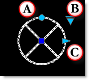 | A.) Rotation Grip - will allow you to rotate the drain as needed to be perpendicular to the pipe B.) Visibility State - will allow you to pick which type of drain you would like to use C.) Stretch to scale grip - will allow you to change how large the drain appears on the drawing. |
THE ROTATION GRIP
Use the rotation grip to align the drain perpendicular to the pipe line. Once rotated to the pipe the pipe can be trimmed to the edges of the drain.
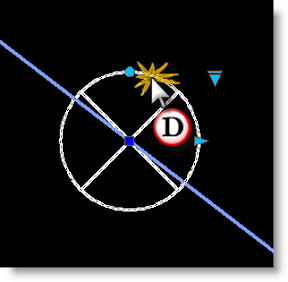 |
| D.) Select the block to show the dynamic block grips |
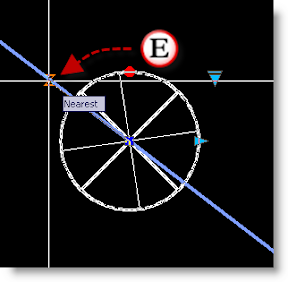 |
| E.) Select the rotation grip to rotate the drain to the pipeline. This will align the drain perpendicular to the pipe. The nearest snap usually works best to snap to the pipe. |
THE VISIBILITY STATE GRIP
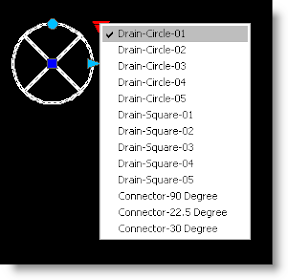
| The visibility grip will allow you to choose which of the drain blocks or utilities to use. There are 10 drains and 3 connector blocks shown once the visibility grip has been clicked on (shown to the right). A list of all the visibility states and their blocks are shown below. The connector blocks are meant to be used after the drain has been placed and rotated to be perpendicular to the pipe. Once, the drain has been placed and rotated, change the visibility state to one of the connectors. With the connector showing, draw a line snapping to the endpoint at the center and at the endpoint of one of the connectors. Change the visibility state back to the drain and use the extend command to extend the line to the next pipe. |
 |
 |
THE STRETCH TO SCALE PROPERTY
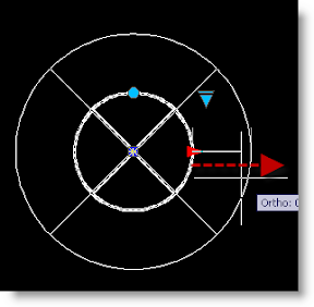 | Use the stretch to scale property to change the size of the drain. This is not meant to be an accurate inch per inch drain, but a representation of where the drain is supposed to go on a large scale drawing. The drain can be scaled in 6" increments. |
Thursday, September 3, 2009
Hatch Patterns That Look Broken
Why Do My Hatch Patterns Look Broken?
The farther away you get from 0,0,0, the harder it is for AutoCAD to process and make accurate calculations. To quote AutoDesk Support,

How Do I Fix The Problem?
A.) Either Double click on the hatch pattern or use the "HATCHEDIT" command and select the hatch pattern you would like to edit.

B.) In the Hatch Origin panel click on the "Click to set new origin".

C.) There is no magic to this, but the point to select for the origin should be somewhere very close to the hatch pattern. I usually pick the lower left corner of the hatch pattern.

Click "OK" and now your hatch pattern should look normal once again.

The farther away you get from 0,0,0, the harder it is for AutoCAD to process and make accurate calculations. To quote AutoDesk Support,
"When objects start to exceed 100,000 or 0.000001 units in precision, the mathematical calculations are at risk to push beyond the processor limitation."
The result is a hatch pattern that looks like the image below.How Do I Fix The Problem?
A.) Either Double click on the hatch pattern or use the "HATCHEDIT" command and select the hatch pattern you would like to edit.
Click "OK" and now your hatch pattern should look normal once again.
Wednesday, September 2, 2009
The Risks Of Copying and Pasting Blocks
Why Do My Blocks Look Different From Drawing To Drawing?
There is one reason really:
The block was already in your drawing and the block has been edited.
The Problem
It is ironic that we create block libraries to develop continuity in our drawings, but because they can be edited, they are one of the items that can cause a lot of problems. The more a block is edited, the higher probability you have some sort of block problem with your drawings (especially if you are collaborating with people within the office). This problem will manifest itself when copying and pasting blocks from one drawing to another.
Block Characteristics
Blocks have this distinct characteristic, "the first block there wins", and by that I mean if an edited block is in the drawing before the standard block, the standard block will look like the edited block. Inserting a block from a palette, pull down menu, or dialog box will not always insert the most current and up-to-date block from the block library. It will only be the most current and up-to-date block, if that block has not been inserted before. If the block has already been placed in that drawing, AutoCAD will continue to use the block already stored in the drawing.
Common Scenario
One of the most common scenarios, is the copying and pasting of plant blocks from one drawing to another. Which block you will see? It all depends on which block was there first (shown below).

A.) The edited block has been turned green
B.) The standard block on the right has been copied.
C.) The standard block has been pasted into the drawing with the edited block. Notice that the standard block now looks like the edited block.
Color is not the only item that can be changed. Changing the scale, insert units, and attributes are all quite common issues as well.
Fixing A Standard Block
To fix a standard block back to the original, use the Update Block command (TBG shortcut "UB"). If the name of the block is the same as the one in our standard library, update block will change all the blocks with that name in the drawing to the original standard block.
Please be aware....
Some blocks may have different insert points (due to editing) and may not appear in the same place. A good example would be updating our "older" spot grade symbol to the "newer" spot grade. They have different insert points. If this happens, just use the undo command to put them back the way they were.
There is one reason really:
The block was already in your drawing and the block has been edited.
The Problem
It is ironic that we create block libraries to develop continuity in our drawings, but because they can be edited, they are one of the items that can cause a lot of problems. The more a block is edited, the higher probability you have some sort of block problem with your drawings (especially if you are collaborating with people within the office). This problem will manifest itself when copying and pasting blocks from one drawing to another.
Block Characteristics
Blocks have this distinct characteristic, "the first block there wins", and by that I mean if an edited block is in the drawing before the standard block, the standard block will look like the edited block. Inserting a block from a palette, pull down menu, or dialog box will not always insert the most current and up-to-date block from the block library. It will only be the most current and up-to-date block, if that block has not been inserted before. If the block has already been placed in that drawing, AutoCAD will continue to use the block already stored in the drawing.
Common Scenario
One of the most common scenarios, is the copying and pasting of plant blocks from one drawing to another. Which block you will see? It all depends on which block was there first (shown below).
A.) The edited block has been turned green
B.) The standard block on the right has been copied.
C.) The standard block has been pasted into the drawing with the edited block. Notice that the standard block now looks like the edited block.
Color is not the only item that can be changed. Changing the scale, insert units, and attributes are all quite common issues as well.
Fixing A Standard Block
To fix a standard block back to the original, use the Update Block command (TBG shortcut "UB"). If the name of the block is the same as the one in our standard library, update block will change all the blocks with that name in the drawing to the original standard block.
Please be aware....
Some blocks may have different insert points (due to editing) and may not appear in the same place. A good example would be updating our "older" spot grade symbol to the "newer" spot grade. They have different insert points. If this happens, just use the undo command to put them back the way they were.
Monday, August 17, 2009
Relative Paths For Reference Files (DWG, JPG, TIFF, DGN, DWF, & PDF)
Relative paths are partially specified folder paths for reference files (DWG, JPG, TIF, DWF, DGN, and PDF's in AutoCAD 2010) that assume drive letter of your current drawing and the common folders (or path) of the current drawing.
Relative paths enable you to:
1. To move a set of drawings from your DD or SD folder set to the CD folder set without having to remap images, drawings, DWF’s, or DGN’s
2. To rename a project folder that uses the same folder structure (if they are already relative xrefs).
3. Allows consultants to keep the same folder structure (or close to it) and find our drawings.
4. Also, makes archiving drawings easier, because the links to the drawing or image paths will not be lost.
All reference files have 2 different paths:
1. "Saved" path
Tells AutoCAD what the path type is. (Relative, Full, or No Path)
2. "Found At" path (is editable and can change the Saved Path)
Is an editable display of where AutoCAD is finding the drawing based on the path type just by clicking on the path. Notice how the two paths differ below.
The 3 ways to make a reference file path a relative path:
1. When inserting the reference file, choose the relative path option. The current drawings must be saved to use this option.
2. Run the Xref Repath command or "XRP" to change existing reference file paths to relative paths. (Click on the images to enlarge)
3. Manually change the “Saved path” by changing the “Found At" path.
How do I manually change my reference path and what do all the symbols mean?
1. Host drawing path (or in other words the drawing you have open for this example is:
"Z:\TBG\Bridgelands\Parkway Planting (A06353)\04 CD\Work\A06353-plant.dwg"
2. In this example, all changes will be made to the xref (or reference file) after it has been inserted into the drawing. These changes will be made in the "Found At" location of the xref dialog box. Once "Enter" is pressed after changing the path, the "Saved Path" location will change to a relative path.
When Folders Are The Same:
3. ".\" (1 period and a backslash) Means the image or drawing is in the same directory as the host drawing listed above, or in other words, the directory path is exactly the same.
Host:
Z:\TBG\Bridgelands\Parkway Planting (A06353)\04 CD\Work\A06353-plant.dwg
Reference:
Z:\TBG\Bridgelands\Parkway Planting (A06353)\04 CD\Work\A06353-site.dwg
That will then leave you no remaining folders. Remember the site file is referenced into the planting file and that is one you are changing. Because these are in the same folder there will only be one (1) period before the backslash. This is the only different one. All other examples follow the pattern below.
".\A06353-site.dwg
When Folders Are Not The Same:
4. "..\" (2 periods and a backslash) Means the image or drawing is in the same directory as the host drawing but one folder was different. You can add as many "..\" as needed like this "..\..\..\" .
Shown below is the host drawing path and the reference path. What a relative path will do is remove the common path shown in light gray below:
Host:
Z:\TBG\Bridgelands\Parkway Planting (A06353)\04 CD\Work\A06353-plant.dwg
Reference:
Z:\TBG\Bridgelands\Parkway Planting (A06353)\04 CD\Xref\A06353-civil.dwg
That will then leave you with the folders in Red. You will then replace each folder with a "..\" Remember the civil file is referenced into the planting file and that is one you are changing.
Work\A06353-Planiting.dwg
"Xref\A06353-civil.dwg" will become "..\A06353-civil.dwg"
Now you have all the information you need to automatically or manually change your reference files.
Relative paths enable you to:
1. To move a set of drawings from your DD or SD folder set to the CD folder set without having to remap images, drawings, DWF’s, or DGN’s
2. To rename a project folder that uses the same folder structure (if they are already relative xrefs).
3. Allows consultants to keep the same folder structure (or close to it) and find our drawings.
4. Also, makes archiving drawings easier, because the links to the drawing or image paths will not be lost.
All reference files have 2 different paths:
1. "Saved" path
Tells AutoCAD what the path type is. (Relative, Full, or No Path)
2. "Found At" path (is editable and can change the Saved Path)
Is an editable display of where AutoCAD is finding the drawing based on the path type just by clicking on the path. Notice how the two paths differ below.
 |
The 3 ways to make a reference file path a relative path:
1. When inserting the reference file, choose the relative path option. The current drawings must be saved to use this option.
 |
2. Run the Xref Repath command or "XRP" to change existing reference file paths to relative paths. (Click on the images to enlarge)
 |  |
3. Manually change the “Saved path” by changing the “Found At" path.
 |
How do I manually change my reference path and what do all the symbols mean?
1. Host drawing path (or in other words the drawing you have open for this example is:
"Z:\TBG\Bridgelands\Parkway Planting (A06353)\04 CD\Work\A06353-plant.dwg"
2. In this example, all changes will be made to the xref (or reference file) after it has been inserted into the drawing. These changes will be made in the "Found At" location of the xref dialog box. Once "Enter" is pressed after changing the path, the "Saved Path" location will change to a relative path.
When Folders Are The Same:
3. ".\" (1 period and a backslash) Means the image or drawing is in the same directory as the host drawing listed above, or in other words, the directory path is exactly the same.
Host:
Z:\TBG\Bridgelands\Parkway Planting (A06353)\04 CD\Work\A06353-plant.dwg
Reference:
Z:\TBG\Bridgelands\Parkway Planting (A06353)\04 CD\Work\A06353-site.dwg
That will then leave you no remaining folders. Remember the site file is referenced into the planting file and that is one you are changing. Because these are in the same folder there will only be one (1) period before the backslash. This is the only different one. All other examples follow the pattern below.
".\A06353-site.dwg
When Folders Are Not The Same:
4. "..\" (2 periods and a backslash) Means the image or drawing is in the same directory as the host drawing but one folder was different. You can add as many "..\" as needed like this "..\..\..\" .
Shown below is the host drawing path and the reference path. What a relative path will do is remove the common path shown in light gray below:
Host:
Z:\TBG\Bridgelands\Parkway Planting (A06353)\04 CD\Work\A06353-plant.dwg
Reference:
Z:\TBG\Bridgelands\Parkway Planting (A06353)\04 CD\Xref\A06353-civil.dwg
That will then leave you with the folders in Red. You will then replace each folder with a "..\" Remember the civil file is referenced into the planting file and that is one you are changing.
Work\A06353-Planiting.dwg
"Xref\A06353-civil.dwg" will become "..\A06353-civil.dwg"
Now you have all the information you need to automatically or manually change your reference files.
Monday, August 10, 2009
AutoCAD - Layer Names and Structure
LAYER STRUCTURE:
The Layer structure at TBG has been organized according to, type of drawing (category), topic (sub-category), and detailed topic (sub-category descriptor), and/or scale specific items. This layering system is a hybrid of our previous system of layering and the AIA standard. The AIA layering standard would have all of our layers starting with "L". The naming structure looks like this:
LAYER NAME & DESCRIPTION
0S-walk-bldr-The first two letters “0S” designate the Classification of the layer
0S-walk-bldr: The next four letters designate the Division. ** The Division should not exceed 4 letters
0S-walk-bldr: The next item we can call the Sub-Division. ** The Sub-Divisions should not exceed 4 letters
0A-note-A-0010: “A” is the Category for that note. There are categories A,B, and C.
0A-strt-0010: ”0010” is the Scale in which that item was drawn. Any layer that has the scale at the end of a layer name is typically called a Dimscale Layer.
The Layer structure at TBG has been organized according to, type of drawing (category), topic (sub-category), and detailed topic (sub-category descriptor), and/or scale specific items. This layering system is a hybrid of our previous system of layering and the AIA standard. The AIA layering standard would have all of our layers starting with "L". The naming structure looks like this:
 |
LAYER NAME & DESCRIPTION
0S-walk-bldr-The first two letters “0S” designate the Classification of the layer
0S-walk-bldr: The next four letters designate the Division. ** The Division should not exceed 4 letters
0S-walk-bldr: The next item we can call the Sub-Division. ** The Sub-Divisions should not exceed 4 letters
0A-note-A-0010: “A” is the Category for that note. There are categories A,B, and C.
0A-strt-0010: ”0010” is the Scale in which that item was drawn. Any layer that has the scale at the end of a layer name is typically called a Dimscale Layer.
Thursday, August 6, 2009
Grading Flow Arrow Dynamic Block
Every once and a while you need a flow arrow to either:
A. Show Direction of a slope
B. Show directioin and size of Pipe
C. Or just show the size of pipe and slope.
You can find the Grading Flow Arrow in several places.
For the command line type "GF".
For the Toolbar Button, it is on the TBG Cadscape - Grading Toolbar
For the Palette, it is on the grading tab
For the pulldown menu, it is on the Construction->Grading-Flow Arrow
The grading arrow (shown below) shows the arrow and how it is to be placed on the pipeline. Once placed on the line, the arrow can be flipped 180 degrees, flipped to the other side of the line, stretched, rotated to match the line, or changed to one of the three visual states that exist on on the flow arrow.
To place a flow arrow with no text on a pool deck or sidewalk just to show the general direction of water flow use the Flow Arrow No Text.
To just add text to a pipe to show size and slope of the pipe use the Piping Text.
If the line moves:
1. Use the base grip to move the arrow by snapping to the new location.
2. Use the rotate grip (shown as a blue circular grip) to rotate the arrow to the new location.
A. Show Direction of a slope
B. Show directioin and size of Pipe
C. Or just show the size of pipe and slope.
You can find the Grading Flow Arrow in several places.
For the command line type "GF".
For the Toolbar Button, it is on the TBG Cadscape - Grading Toolbar
For the Palette, it is on the grading tab
For the pulldown menu, it is on the Construction->Grading-Flow Arrow
 |
The grading arrow (shown below) shows the arrow and how it is to be placed on the pipeline. Once placed on the line, the arrow can be flipped 180 degrees, flipped to the other side of the line, stretched, rotated to match the line, or changed to one of the three visual states that exist on on the flow arrow.
 |
To place a flow arrow with no text on a pool deck or sidewalk just to show the general direction of water flow use the Flow Arrow No Text.
 |
To just add text to a pipe to show size and slope of the pipe use the Piping Text.
 |
If the line moves:
1. Use the base grip to move the arrow by snapping to the new location.
2. Use the rotate grip (shown as a blue circular grip) to rotate the arrow to the new location.
 |
Tuesday, August 4, 2009
Exporting an AutoCAD Table to Excel
You can export a AutoCAD Table to Excel with a few easy steps.
1. You will need to have your right click set up for the short cut menu option.
A.. Type "OP" or "Options" on the command line.
B. Go to the "User Preferences" tab.
C. Click on "Right Click Options"
D. Check the "Enable Shortcut Menu"
2. Select the outer boundary of the table. Do not select a cell only, this will not work. You will need to select the entire table for the shortcut menu to appear.
3. Select "Export" on the shortcut menu to export the table to .csv or (Comma Seperated Values) which Microsoft Excel can read. If you open up a .csv file with notepad, will will see every cell that was in table is seperated by commas. When opened with Excel, it will interpret the data into columns and rows.
4. Once the file has been exported. Either open Excel and open the .csv file or double click on the .csv file to open it (it should default to Excel).
5. Now you have successfully exported an AutoCAD Table to Excel.
1. You will need to have your right click set up for the short cut menu option.
A.. Type "OP" or "Options" on the command line.
B. Go to the "User Preferences" tab.
C. Click on "Right Click Options"
D. Check the "Enable Shortcut Menu"
 |
| From TBG's Two Minute Training |
2. Select the outer boundary of the table. Do not select a cell only, this will not work. You will need to select the entire table for the shortcut menu to appear.
 | Notice that only the cell is slected and not the entire table. If you have selected a cell by accident then hit ESC a couple of times and try selecting the outer border again. |
 | This table has been selected. You can tell the difference by noticing how everything in the table is highlighted. Once everything is highlighted, right click to bring up the shortcut menu. |
3. Select "Export" on the shortcut menu to export the table to .csv or (Comma Seperated Values) which Microsoft Excel can read. If you open up a .csv file with notepad, will will see every cell that was in table is seperated by commas. When opened with Excel, it will interpret the data into columns and rows.
 | Once "Export" is clicked on it will ask you where to save your file. Select your project folder and place it in the appropriate folder |
4. Once the file has been exported. Either open Excel and open the .csv file or double click on the .csv file to open it (it should default to Excel).
5. Now you have successfully exported an AutoCAD Table to Excel.
Subscribe to:
Posts (Atom)