

Linetype Standards
We don't have many office standards governing linetypes, just three really.
1. All Colors for objects (except for details) should be "ByLayer".
1. All Linetypes for objects (except for details) should be "ByLayer".
2. All Linetypes (except for details) should have a scale of 1. (Variable "celtscale" or current element linetype scale.)
That's not too hard.
Why can I not match properties to a linetype?
There are a few reasons:
1.) Either the MatchProp settings do not include Linetype
2.) We do not have that linetype in our library and will not match properties to it.
Why are details exempt from being ByLayer?
The main reason that object colors and linetypes are exempt from being ByLayer in details is because details are not externally referenced into other types of drawings. Details are drawn as what you see is what you get.
Why can I not see my linetype correctly?
There can be several reasons.
1.) You are drawing a line while CELTSCALE =1 the properties palette and looking at the linetype scale.
2.) Make sure the linetype is ByLayer..
3.) Make sure it is a linetype we have. Just because a linetype appears in a drawing does not mean we have it.
4.) Choose a smaller or larger linetype, and do not change the LTSCALE.
6.) Use the layer dialog and make sure it is assigned the correct linetype.
Why will the colors not stay when I apply them to an xref?
The variable "visretain" is set to 0. It needs to be set to 1.
Why can I not change the color of the object in my xref using the layer dialog?
Because the object in the referenced drawing is not set to ByLayer?
Tuesday, February 2, 2010


Two Minute Training Blog Updates
There have been a few changes to the Two Minute Training Blog.
- The labels have been reorganized according to topic such as, Program Type, How To Articles, Commands, and Standards.
- This will end up being our CAD Manual organized by topic and searchable.
- Now, would be a good time to brush up and refresh your knowledge of the office standards as these are published.
- If you would like to know more about a topic, problem, need a standard, or don't like a standard (maybe it's something we need to revisit) please send your CAD Manger an email or just leave a comment on the blog. (They are moderated so they do not appear immediately).
Multiple e-mail issue:
Sorry for the technical issue contributing to the multiple e-mails that was not meant to happen.
- The labels have been reorganized according to topic such as, Program Type, How To Articles, Commands, and Standards.
- This will end up being our CAD Manual organized by topic and searchable.
- Now, would be a good time to brush up and refresh your knowledge of the office standards as these are published.
- If you would like to know more about a topic, problem, need a standard, or don't like a standard (maybe it's something we need to revisit) please send your CAD Manger an email or just leave a comment on the blog. (They are moderated so they do not appear immediately).
Multiple e-mail issue:
Sorry for the technical issue contributing to the multiple e-mails that was not meant to happen.
Monday, February 1, 2010
Using Make Single Project Directory - "SPJ"
Where to find the SPJ command:
1. Pulldown menu: File->New Single Project
2. Ribbon menu: Title->New Projects->Single Project
3. Command Line: "SPJ"
What does New Single Project do exactly?
- Creates the primary folder with the project name and the job number.
- Creates all the sub-folders that are needed for a project
- Creates all the blank CAD drawings with the correct job numbers
- Creates the sheet set needed for the project with the job number.
- Will include folder updates that have been approved by the CAD Steering Committee.
FAQ's
Why do we use the SPJ command?
- Because there is a lot to remember when making a new project folder, the SPJ command will create all the necessary folders and start up files you will need for the project.
Why do we have to use AutoCAD to make the new project directory? I don't start a project using AutoCAD.
- Right now, this is the only way to ask for input and apply that to information to new project folders, files, and other information.
Why can't I just make a folder to copy over and over again for new projects?
- We could do it that way, but what the SPJ command does for you is rename all the folders and files based that project number. This saves you a lot of time.
What if someone made the job folder, but didn't include all right folders and files information?
- Run SPJ and use the exact same project name. It will create the correct folder structure and will not overwrite or delete existing information. This will also give you all your standard folder and file names with the job number.
What if the project does not have a job number?
- Every project should have a job number. If the folder does not have the project number and has work in it, then when it gets a job number add the job number to the folder and repath all the linked files. The sooner you do this the better.
1. Pulldown menu: File->New Single Project
2. Ribbon menu: Title->New Projects->Single Project
3. Command Line: "SPJ"
What does New Single Project do exactly?
- Creates the primary folder with the project name and the job number.
- Creates all the sub-folders that are needed for a project
- Creates all the blank CAD drawings with the correct job numbers
- Creates the sheet set needed for the project with the job number.
- Will include folder updates that have been approved by the CAD Steering Committee.
FAQ's
Why do we use the SPJ command?
- Because there is a lot to remember when making a new project folder, the SPJ command will create all the necessary folders and start up files you will need for the project.
Why do we have to use AutoCAD to make the new project directory? I don't start a project using AutoCAD.
- Right now, this is the only way to ask for input and apply that to information to new project folders, files, and other information.
Why can't I just make a folder to copy over and over again for new projects?
- We could do it that way, but what the SPJ command does for you is rename all the folders and files based that project number. This saves you a lot of time.
What if someone made the job folder, but didn't include all right folders and files information?
- Run SPJ and use the exact same project name. It will create the correct folder structure and will not overwrite or delete existing information. This will also give you all your standard folder and file names with the job number.
What if the project does not have a job number?
- Every project should have a job number. If the folder does not have the project number and has work in it, then when it gets a job number add the job number to the folder and repath all the linked files. The sooner you do this the better.
Tuesday, January 19, 2010
FTP Sites and Internet Explorer
I will show you how to change the view from "Internet Explorer" to a "Windows Explorer" view. I wanted to give you a couple of options for logging on to FTP sites.
Option #1 - Using Windows Explorer Instead of Internet Explorer (Preferred Option)
A. Open "Windows Explorer" first (not Internet Explorer). You can access "Windows Explorer" by 1.) Right Clicking on "My Computer" and selecting "Explore"; or 2.) pressing the "Windows Key"+"E" simultaneously.
B. Type in the FTP address in the address bar. (example ftp://192.168.0.251/)
C. This will open the FTP log on screen.
D. After you select "Open FTP Site in Windows Explorer" you will see the window change to the "Windows Explorer" format with the FTP icon in the address bar along with the FTP log on Screen.
E. Type in the the same "User name" and "Password" that you used before. This is the SECOND log on.
F. Do not...check the "Save Password". This will save you a lot of headaches later on because you may want to log on to other FTP sites later.
G. Click "Log On".
Option #2 - Using Internet Explorer
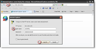
A. Log on to the FTP site by entering the FTP address (for this example I will use "ftp://192.168.0.251/ which is our local FTP address")
B. Enter the "User name" and "Password" of the FTP site. (In this case, the local FTP user name and password are provided on theHub.)
C. Click "Log On". This is the FIRST log on and takes you to the "Internet Explorer FTP View".
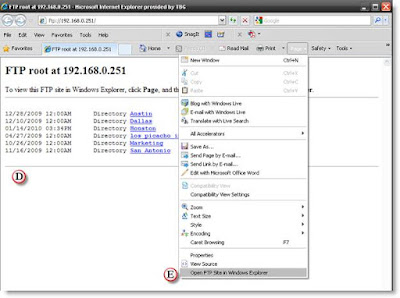
D. This Internet Explorer view will look a lot like a web page with links to the folders.
E. To get the "Windows Explorer" view click on the "Page" pull down menu and select "Open FTP Site in Windows Explorer". You will only see this menu option when you are viewing an FTP site.
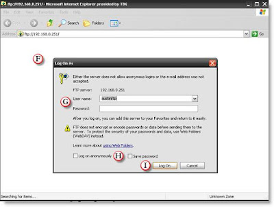
F. After you select "Open FTP Site in Windows Explorer" you will see the window change to the "Windows Explorer" format with the FTP icon in the address bar along with the FTP log on Screen.
G. Type in the the same "User name" and "Password" that you used before. This is the SECOND log on.
H. Do not...check the "Save Password". This will save you a lot of headaches later on because you may want to log on to other FTP sites later.
I. Click "Log On".
J. This will bring you to the "Windows Explorer" view of the FTP site.
A New Additional Setting for Internet Explorer 8 and 9
If you are still having issues getting onto someone's ftp site then try changing the Passive FTP setting as shown below.
A. Go to Tools->Internet Options->Advanced Tab
B. Scroll down until you find "Use Passive FTP (for firewall and DSL modem campatibility), and unselect that option if it is selected.
Option #1 - Using Windows Explorer Instead of Internet Explorer (Preferred Option)
A. Open "Windows Explorer" first (not Internet Explorer). You can access "Windows Explorer" by 1.) Right Clicking on "My Computer" and selecting "Explore"; or 2.) pressing the "Windows Key"+"E" simultaneously.
B. Type in the FTP address in the address bar. (example ftp://192.168.0.251/)
C. This will open the FTP log on screen.
D. After you select "Open FTP Site in Windows Explorer" you will see the window change to the "Windows Explorer" format with the FTP icon in the address bar along with the FTP log on Screen.
E. Type in the the same "User name" and "Password" that you used before. This is the SECOND log on.
F. Do not...check the "Save Password". This will save you a lot of headaches later on because you may want to log on to other FTP sites later.
G. Click "Log On".
Option #2 - Using Internet Explorer
A. Log on to the FTP site by entering the FTP address (for this example I will use "ftp://192.168.0.251/ which is our local FTP address")
B. Enter the "User name" and "Password" of the FTP site. (In this case, the local FTP user name and password are provided on theHub.)
C. Click "Log On". This is the FIRST log on and takes you to the "Internet Explorer FTP View".
D. This Internet Explorer view will look a lot like a web page with links to the folders.
E. To get the "Windows Explorer" view click on the "Page" pull down menu and select "Open FTP Site in Windows Explorer". You will only see this menu option when you are viewing an FTP site.
F. After you select "Open FTP Site in Windows Explorer" you will see the window change to the "Windows Explorer" format with the FTP icon in the address bar along with the FTP log on Screen.
G. Type in the the same "User name" and "Password" that you used before. This is the SECOND log on.
H. Do not...check the "Save Password". This will save you a lot of headaches later on because you may want to log on to other FTP sites later.
I. Click "Log On".
J. This will bring you to the "Windows Explorer" view of the FTP site.
A New Additional Setting for Internet Explorer 8 and 9
If you are still having issues getting onto someone's ftp site then try changing the Passive FTP setting as shown below.
A. Go to Tools->Internet Options->Advanced Tab
B. Scroll down until you find "Use Passive FTP (for firewall and DSL modem campatibility), and unselect that option if it is selected.
 |
| From TBG Two Minute Training |
Thursday, October 8, 2009
Dynamic Drain Block
The Dynamic Drain block is meant to be used in our grading plans. It is a dynamic block that will allow you choose from 10 different drain symbols and 3 pipe connectors. It can be inserted from several places:

THE DYNAMIC BLOCK PROPERTIES
Once the drain block has been inserted into the drawing, click on the block to reveal the light blue dynamic block grips.
THE ROTATION GRIP
Use the rotation grip to align the drain perpendicular to the pipe line. Once rotated to the pipe the pipe can be trimmed to the edges of the drain.
THE VISIBILITY STATE GRIP
THE STRETCH TO SCALE PROPERTY
- Construction->Grading -Drains pulldown menu
- Keyboard command: "Drain"
- Toolpalette->Grading Tab
- Grading Toolbar (shown below)
THE DYNAMIC BLOCK PROPERTIES
Once the drain block has been inserted into the drawing, click on the block to reveal the light blue dynamic block grips.
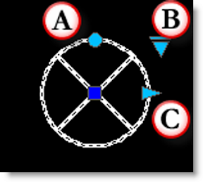 | A.) Rotation Grip - will allow you to rotate the drain as needed to be perpendicular to the pipe B.) Visibility State - will allow you to pick which type of drain you would like to use C.) Stretch to scale grip - will allow you to change how large the drain appears on the drawing. |
THE ROTATION GRIP
Use the rotation grip to align the drain perpendicular to the pipe line. Once rotated to the pipe the pipe can be trimmed to the edges of the drain.
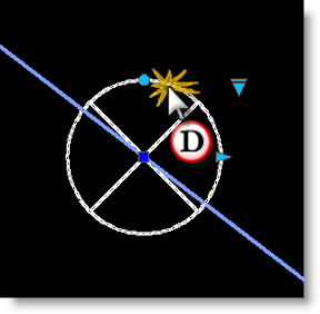 |
| D.) Select the block to show the dynamic block grips |
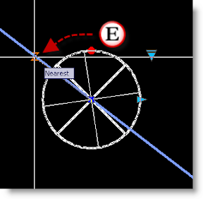 |
| E.) Select the rotation grip to rotate the drain to the pipeline. This will align the drain perpendicular to the pipe. The nearest snap usually works best to snap to the pipe. |
THE VISIBILITY STATE GRIP
| The visibility grip will allow you to choose which of the drain blocks or utilities to use. There are 10 drains and 3 connector blocks shown once the visibility grip has been clicked on (shown to the right). A list of all the visibility states and their blocks are shown below. The connector blocks are meant to be used after the drain has been placed and rotated to be perpendicular to the pipe. Once, the drain has been placed and rotated, change the visibility state to one of the connectors. With the connector showing, draw a line snapping to the endpoint at the center and at the endpoint of one of the connectors. Change the visibility state back to the drain and use the extend command to extend the line to the next pipe. |
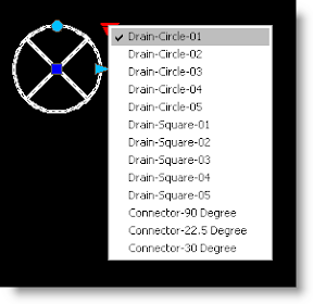 |
 |
THE STRETCH TO SCALE PROPERTY
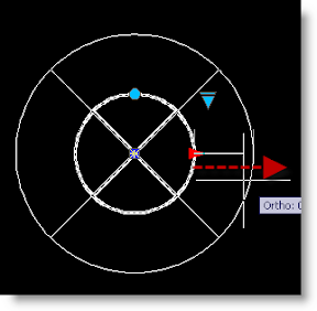 | Use the stretch to scale property to change the size of the drain. This is not meant to be an accurate inch per inch drain, but a representation of where the drain is supposed to go on a large scale drawing. The drain can be scaled in 6" increments. |
Thursday, September 3, 2009
Hatch Patterns That Look Broken
Why Do My Hatch Patterns Look Broken?
The farther away you get from 0,0,0, the harder it is for AutoCAD to process and make accurate calculations. To quote AutoDesk Support,

How Do I Fix The Problem?
A.) Either Double click on the hatch pattern or use the "HATCHEDIT" command and select the hatch pattern you would like to edit.

B.) In the Hatch Origin panel click on the "Click to set new origin".

C.) There is no magic to this, but the point to select for the origin should be somewhere very close to the hatch pattern. I usually pick the lower left corner of the hatch pattern.

Click "OK" and now your hatch pattern should look normal once again.

The farther away you get from 0,0,0, the harder it is for AutoCAD to process and make accurate calculations. To quote AutoDesk Support,
"When objects start to exceed 100,000 or 0.000001 units in precision, the mathematical calculations are at risk to push beyond the processor limitation."
The result is a hatch pattern that looks like the image below.How Do I Fix The Problem?
A.) Either Double click on the hatch pattern or use the "HATCHEDIT" command and select the hatch pattern you would like to edit.
Click "OK" and now your hatch pattern should look normal once again.
Wednesday, September 2, 2009
The Risks Of Copying and Pasting Blocks
Why Do My Blocks Look Different From Drawing To Drawing?
There is one reason really:
The block was already in your drawing and the block has been edited.
The Problem
It is ironic that we create block libraries to develop continuity in our drawings, but because they can be edited, they are one of the items that can cause a lot of problems. The more a block is edited, the higher probability you have some sort of block problem with your drawings (especially if you are collaborating with people within the office). This problem will manifest itself when copying and pasting blocks from one drawing to another.
Block Characteristics
Blocks have this distinct characteristic, "the first block there wins", and by that I mean if an edited block is in the drawing before the standard block, the standard block will look like the edited block. Inserting a block from a palette, pull down menu, or dialog box will not always insert the most current and up-to-date block from the block library. It will only be the most current and up-to-date block, if that block has not been inserted before. If the block has already been placed in that drawing, AutoCAD will continue to use the block already stored in the drawing.
Common Scenario
One of the most common scenarios, is the copying and pasting of plant blocks from one drawing to another. Which block you will see? It all depends on which block was there first (shown below).

A.) The edited block has been turned green
B.) The standard block on the right has been copied.
C.) The standard block has been pasted into the drawing with the edited block. Notice that the standard block now looks like the edited block.
Color is not the only item that can be changed. Changing the scale, insert units, and attributes are all quite common issues as well.
Fixing A Standard Block
To fix a standard block back to the original, use the Update Block command (TBG shortcut "UB"). If the name of the block is the same as the one in our standard library, update block will change all the blocks with that name in the drawing to the original standard block.
Please be aware....
Some blocks may have different insert points (due to editing) and may not appear in the same place. A good example would be updating our "older" spot grade symbol to the "newer" spot grade. They have different insert points. If this happens, just use the undo command to put them back the way they were.
There is one reason really:
The block was already in your drawing and the block has been edited.
The Problem
It is ironic that we create block libraries to develop continuity in our drawings, but because they can be edited, they are one of the items that can cause a lot of problems. The more a block is edited, the higher probability you have some sort of block problem with your drawings (especially if you are collaborating with people within the office). This problem will manifest itself when copying and pasting blocks from one drawing to another.
Block Characteristics
Blocks have this distinct characteristic, "the first block there wins", and by that I mean if an edited block is in the drawing before the standard block, the standard block will look like the edited block. Inserting a block from a palette, pull down menu, or dialog box will not always insert the most current and up-to-date block from the block library. It will only be the most current and up-to-date block, if that block has not been inserted before. If the block has already been placed in that drawing, AutoCAD will continue to use the block already stored in the drawing.
Common Scenario
One of the most common scenarios, is the copying and pasting of plant blocks from one drawing to another. Which block you will see? It all depends on which block was there first (shown below).
A.) The edited block has been turned green
B.) The standard block on the right has been copied.
C.) The standard block has been pasted into the drawing with the edited block. Notice that the standard block now looks like the edited block.
Color is not the only item that can be changed. Changing the scale, insert units, and attributes are all quite common issues as well.
Fixing A Standard Block
To fix a standard block back to the original, use the Update Block command (TBG shortcut "UB"). If the name of the block is the same as the one in our standard library, update block will change all the blocks with that name in the drawing to the original standard block.
Please be aware....
Some blocks may have different insert points (due to editing) and may not appear in the same place. A good example would be updating our "older" spot grade symbol to the "newer" spot grade. They have different insert points. If this happens, just use the undo command to put them back the way they were.
Subscribe to:
Posts (Atom)